Communications Drawing Tool in MCC and LVA (Meter,
Ethernet Switch or PXG900)
This job aid provides an overview of the Product-In-Product (PiP) method of selecting and pricing electronic metering and ethernet switches for the Motor Control Centers (MCC) and Power Xpert Gateway 900 (PXG900) in Low Voltage Assemblies.
For a deeper dive into all the configurators that have the PIP method of selecting and pricing electronic metering and ethernet switches, you can view a series of “how to” videos on the Bid Manager Help site. These videos cover the configurators for MVC, MVA/MEF, MCC, LVA and Switchboards. Navigate to the help site and select Take-off Guides then Enhanced Communication Videos.
Procedures in this Job Aid:
b. Displaying Communication Interconnection Diagrams
MCC: Select Meter or Ethernet Switch
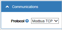
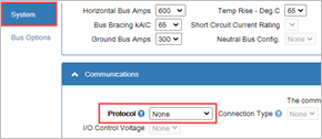
1. If the job calls for the devices in this MCC to communicate with something (e.g. Building Management Systems / Building Automation System [BMS/BAS], Distributed Control System [DCS], Programmable Logic Controller [PLC], Remote Terminal Unit [RTU], Supervisory Control And Data Acquisition [SCADA]), select the protocol required from the Communications / Protocol menu under the System tab.
2. Choose one of the specified protocols.

Note: Selecting ![]() symbol
will direct you to a tutorial for these protocols.
symbol
will direct you to a tutorial for these protocols.
3. The Communications tab appears when you choose any Protocol. If a device is selected that does not support the selected protocol, Bid Manager will warn the user to either replace the device or to include a protocol converter.
Metering
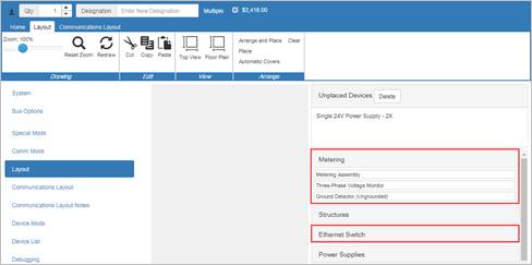
1. To add a Metering or Ethernet switch, click either Metering or Ethernet Switch.
2. For Meters: click on Configure Digital Meter
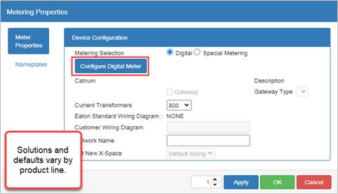
3. Select the meter family.

Note: Click on the ![]() symbol
next to Meter Family will direct you
to a web page that will describe each meter family and model.
symbol
next to Meter Family will direct you
to a web page that will describe each meter family and model.
4. A default meter appears with a factory recommended list of options. Change as desired. A 24 Vdc power supply will be added - this can be deleted
5. Automatically
place the meter with Arrange and Place.
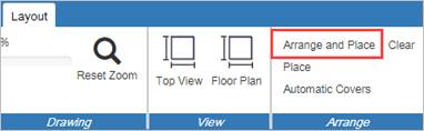
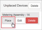
6. Optionally,
you can hover over the Metering Assembly – 1X choice and selecting
the Place button.
7. You
can edit the meter selection by double clicking the meter and selecting
Meter Properties (Metering Assembly).

8. When editing your properties, you may see that you cannot enable the device for network connection as in the image 1 below. This result comes from not selecting a protocol during the initial set up on the System tab as the default for this is None (see image 2).
image 1

image 2
Ethernet Switches
1. Begin by selecting Ethernet Switch from the Layout tab.
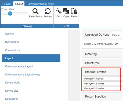
2. Select either a Managed or Unmanaged Ethernet switch and the number of “nodes”. Nodes are the number of devices in the MCC that would connect to the switch.
Note: If the external protocol is chosen as Ethernet/IP, managed switches are required. Otherwise, managed switches are optional, but you will need to provide additional features such as ability to do network redundancy by connecting the nodes in a loop. Contact plant for more details.
3. Some switches can provide extra fiber optic connections.
Low Voltage Assemblies: Select Meter, Ethernet Switch or PXG900
Selecting meters, Ethernet switches and the PXG900 in LVA is very similar to the Motor Control Center takeoff. There is one additional item: the selection of PXG900 gateways.
For LVA, Magnum DS breakers with Digitrip 520MCs or Digitrip 1150s are very common and therefore we have the need for the PXG900 gateway to translate INCOM to something more universal (e.g. BACnet/IP).
1. As with MCCs, select the desired external protocol from the Communications section under the System tab. This specifies the protocol that an external system will use to connect with this LVA line-up. It does not necessarily specify what protocols are used internal to an LVA line-up as gateways (e.g. PXG-900) may be used to convert an internal protocol such as Modbus RTU or INCOM to an external protocol specified here (e.g. BACnet/IP or Modbus TCP).
2. 
3. Additionally, for two of the Ethernet based protocols, BACnet/IP and Modbus TCP, you have the option of specifying whether the connection on the gear is copper (RJ-45) or fiber optic. Only ST connectors are supported in this pull-down. If another type of fiber connection is required [SC, LC, etc.] or if managed switches [e.g. for redundant Ethernet loop connections] are needed, consult the factory for pricing and availability.
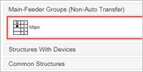
4. On the Layout tab select the Main feeder group.

5. The selection screen uses the same PIP metering module shown earlier in the MCC configurator.
6. Double-click on the metering compartment and this Main Metering Properties screen will display.
Select Meter
1. From the Main Metering Properties, click the Configure Digital Meter button to reveal the Metering window.
2. Make selections under the Meter Family drop-down and the Model Series drop-down.

3. Select the model and options as desired. If a meter doesn’t appear on this list, contact the product line for pricing and availability assistance.
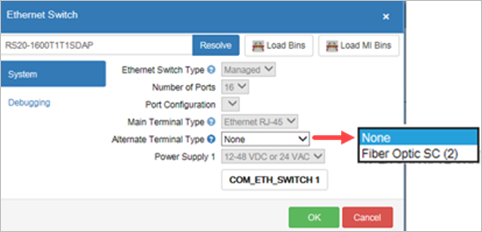
Select Ethernet Switch
1. From the Main Meter Properties window, click the Configure
Ethernet Switch button. The following window will appear.

2. The
options are unmanaged switches with either 4, 6 or 8 Ethernet ports. If
the 6-port switch is selected, you have the option of selecting that either
1 or 2 of the ports can be fiber optic with type LC connectors.

Note: The Connection Type selection made from
the System Tab does not override or inhibit the ability to select either
copper or fiber here.
Power Xpert Gateway 900 (PXG900)
1. Click to place a checkmark next to the Gateway selection in the Main Metering Properties screen.
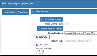
Note: Besides a Main Meter, the LVA configurator has historically
allowed selecting metering within an Incoming Compartment chosen as Feeders
Only in the System tab.
![]()
2. Select the Incoming Cable Taps cell on the front elevation diagram.
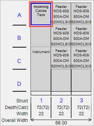
3. This brings up the Incoming Properties window. Select Incoming Metering.

Note: Follow the same procedures as for the Main Metering (selecting meter, Ethernet switch or Gateway). The catalog number for the selected Meter and/or Ethernet switch are displayed in the locations highlighted above.
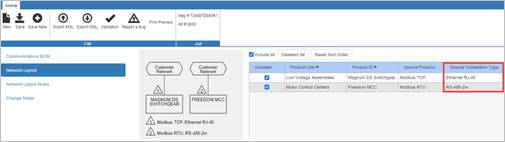
The Communications Layout tab allows for displaying internal communicating devices and their interconnections with ability to customize position, addressing, name plate data and protocols. Examples below.

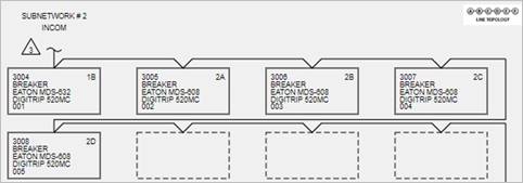
Displaying Communication Interconnection Diagrams
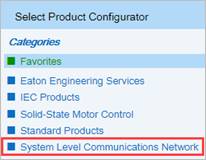
This feature allows creating either a tabular or graphical diagram of communication connections external to and between assemblies. With an alternate selected in the Job screen, click on the Create Item icon to open the New Item window and the choose the System Level Communications Network.
4. 
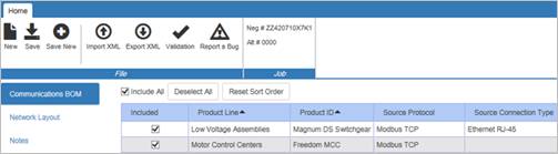
1. The line-ups that included an external protocol Modbus TCP (and not set to None) will appear in this table. This means if you have not set a protocol on the Communications section of the System tab, that line-up will not appear on this list.
2. Click on the Network Layout tab to view the information graphically. This diagram gives the contractor or user information regarding the external communication network connections to the equipment. The diagram shows the wiring and connector types required to connect the communication networks to external equipment.